OPERATION INSTRUCTIONS
PLEASE TAKE 1O MINUTES TO READ COMPLETELY BEFORE 1ST USE.
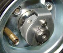
The Retro-fit Drive System (RDS) utilizes a differential/transaxle, when used with the Industry Assist patented drive hub & locking drive collar, it gives the user the option of using the motor & brake or “true neutral” completely disengaged. In short, the hubs use a drive system to lock the wheels to the shaft for our powered hand truck. When not engaged the wheels spin freely. Should the battery lose power, the user will never be stranded. | |
INNER GROOVE ON TRANSAXLE SHAFT IS ENGAGED (or locked) | |
 |  |
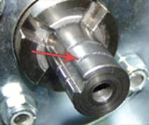
OUTER GROOVE ON TRANSAXLE SHAFT IN DISENGAGED (or unlocked) | |
 |  |
The water resistant sealed ON/OFF switch is located on the top right side. 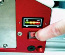 For safety reasons and to prolong the life of your battery, internal controller will automatically turn power OFF after 30 minutes of non-use. To reset just turn switch OFF and then ON again. | |
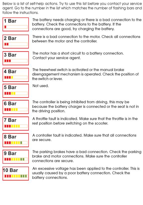
The Trucharge indicator/diagnostic multicolored LED display is located on the top right side next to the ON/OFF switch. 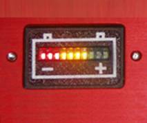 Turning ON the power the Trucharge indicator/diagnostic display will test the entire system for any faults before allowing the user to operate. This takes only 1 second and is usually done by the time the operator has put finger on the throttle. If display flashes, see “troubleshooting” below. After system has performed the diagnostic the Trucharge reverts to a Battery level display. There is also a digital voltage readout located on the other side of the RDS unit. | |
The throttle is located on the underside of the hand grip. 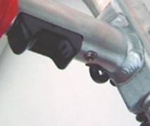 For powered operation of the system push finger throttle in the direction you wish to move. The throttle is true variable speed and will speed-up or slow-down according to how much pressure is applied. When the throttle is let-go it will automatically “return to center” and the hand truck will slow-down and activate the electric brake. When throttle is not engaged the electric brake is activated automatically. There are two (2) settings for the throttle…fast mode and slow mode. This is discussed next. | |
The fast/slow toggle switch is located on the underside of the hand grip, next to the Throttle.  The fast/slow switch allows the user to select one of two modes: For Slow mode the toggle switch is set to the left side position. Slow is for variable speed zero to 2 mph forward or reverse. For Fast mode the toggle switch is set to the right side position. Fast is for variable speed zero to 4 mph (forward or reverse). | |
The AC port for charging is located on the left side. Using a common computer cord, just plug into any common household outlet rated from 110volts to 240volts. 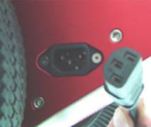 The onboard charging system can be used anywhere in the world. The 24 volt, 2 amp charger will completely charge the battery from dead to completely full in 2 hours. The charger also incorporates inhibit wiring, keeping the system from operation while charging. Also the charger goes into a float charge mode when full. User is completely safe from overcharging. Some systems have the optional VOLTMETER. The voltmeter is located near the AC Port and allows the user to monitor actual voltage to the battery. | |
The optional digital VOLTMETER is located on the left side of the RDS unit.  The digital voltmeter reads DC voltage from 14volts to 40volts. A typical charge will be at maximum capacity around 27.6volts. Voltage below 20volts and the system will not operate efficiently. You will notice the charger sometimes spikes to 28.8volts, this is the charger refreshing the chemicals within the battery. | |
Access to the BATTERY is by the BATTERY DOOR located on the right side. The battery door is fastened to the left side bulkhead by four screws.  The screws are held in place with retaining clips making sure they are not lost. Loosen the four screws in a diagonal pattern to keep even and keep the retaining clips on the screws. Remove battery door. Note how the +/- connector is between the battery and the door. This acts as a shock absorber between the battery and door. The battery will easily slide out. There are springs on the inside. Similar to a flashlight. Reverse the process to install the battery, remember that the +/- connector goes between the battery and door. This acts as a shock absorber. 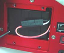
| |
The wheels used must be split rim 4-bolt hole style. This is the most common used wheel in professional applications. The split rim allows the inner tube to be replaced, the solid rims do not. 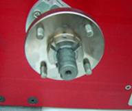 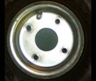 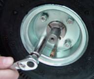
| |
Inflate tires to indicated rating on side of tire. Generally this is 50 U.S. pounds on quality tires, 40 pounds on lower grade brands. 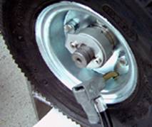
| |
| |
| |
| |